English
 Русский
 Español
 العربية
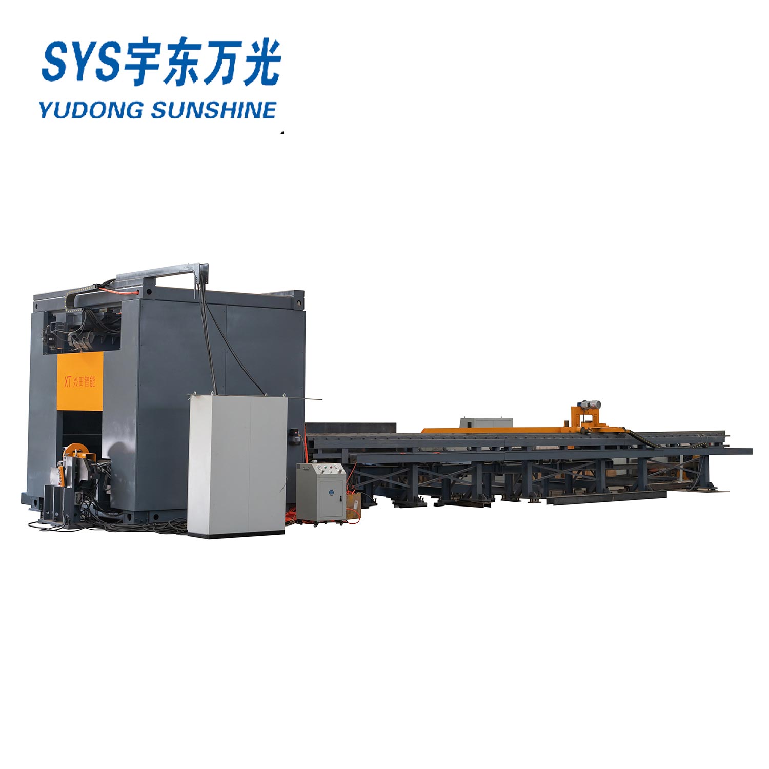
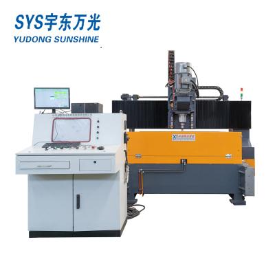
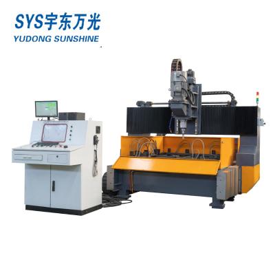
Beam Drilling Machine
The production line is mainly used in drilling and sawing of H beam, U beam which are applied in the fields, such as construction, bridge, boiler, stereo garage, offshore drilling platform and, specially, in steel structure which requires high precision and easy operation. This is machine is necessary for steel structure fabrication.
The combination production line consists of XT-SWZ1250 drilling line and XT-YJC1250 Band Saw, two pairs of infeed in and outfeed conveyors ,and one CNC control device and two side conveyors, along with electrical system, hydraulic system, air cooling and lubrication.
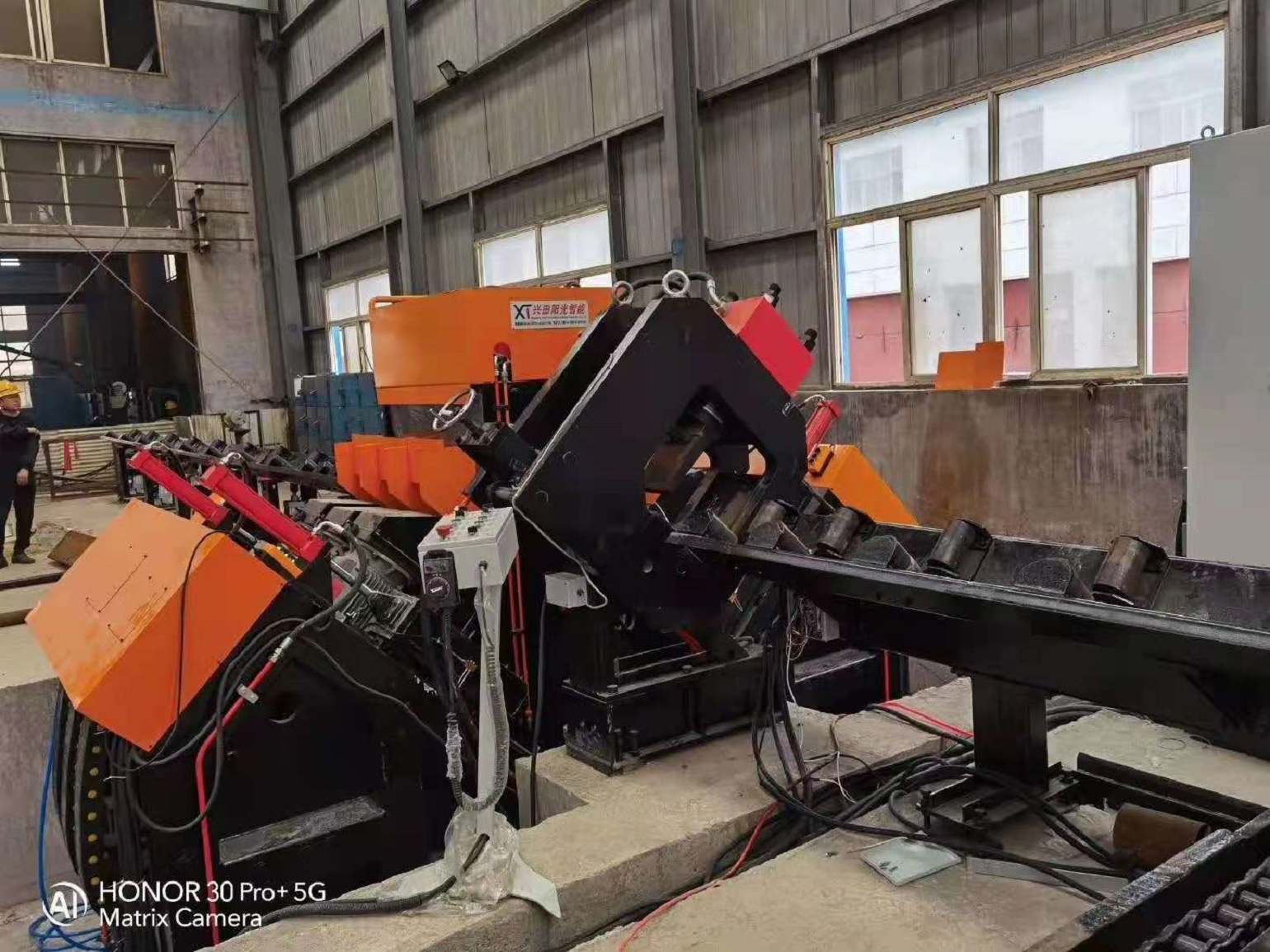
The combination line adopts Z form arrangement that the drilling line and the band saw are installed in parallel and connected by transverse conveyor. Each of the two infeed conveyors equips a NC feeder dolly with servo motor on the datum side and side push device to push the workpiece to the datum side; the drilling line equips an automatic transverse conveyor to upload workpiece; the outfeed conveyor equips roller to move the workpiece out of the process zone and to the transverse conveyor.
In the working process, the personal should lift the workpiece to the automatic transverse conveyor, after the workpiece is uploaded to the infeed conveyor from the transverse conveyor, the side push moves the workpiece to to the datum side, and the dolly moves the workpiece to the processing zone to drill, after the drilling, the roller moves the workpiece to the outfeed conveyor, the transverse conveyor which connects drilling line and band saw moves the workpiece from the outfeed of the drilling line to the infeed of the band saw to cut the workpiece, after the cutting the workpiece is downloaded to the outfeed, and the transverse conveyor of the band saw moves the workpiece out of the processing zone.
The process sequence is from drilling to cutting, the long workpiece which is meant to process into several pieces can be drilled integrally and then cut in to pieces. The transverse conveyor between two lines in Z form arrangement can can adjust the process speed. The Z form arrange let these two lines work both together and separately, when one of them is in maintaining the another line can work independently.

1. Configuration
The combination line line includes dolly, dolly track, feed conveyor, feeding line, SWZ1250 drilling line, YJC1250 band saw, electrical control system, hydraulic system, air cooling system, lubrication and etc.
Terms to explain:
1. Dolly: driven by servo motor with gear box via rack and pinion, the workpiece is clamped by the jaw in order to lengthwise infeed and positioning.
2. Dolly track: bear dolly to infeed, this track can by customized.
3. Feed conveyor: consist of infeed conveyor and outfeed conveyor to bear and output the workpiece.
4. Feeding line: this transverse line consists of four in feed frames to automatically upload workpiece.
5. SWZ1250 drilling line: 3D drilling machine has three drilling heads with spindle. The side drilling head has vertical positioning, and vertical drilling head has radial positioning.
6. YJC1250 Band saw: equip two-pillar-closed structure, linear guide, possess high stiffness and efficiency.
7. Hydraulic system: equip with oil tank, low pressure pump set, cooler, main valve block and other control valve unit.
8. Electrical control system: with PLC and computer, two sets of it.
9. Hydraulic system: control hydraulic movements and support hydraulic power.
10. Air cooling system: adopt mist cooling for drilling line, band saw adopts water cooling.
11. Lubrication: VERSA lubricating system, support linear guide, guide screw, bearing and etc., some other parts of this line apply artificial lubricating.
Please see the attachment of arrangement.
1. Main Specification:
| Model | SWZ1250 | ||||
| Workpiece size | H Beam | Web x Flange (mm) | 150x80~1250x600 | ||
| U Beam | WebxFlange (mm) | 150x80~1250x400 | |||
| Box Beam | WebxFlange (mm) | 150x80~1250x400 | |||
| Angle Beam | WebxFlange (mm) | 200x200x16 | |||
| Max. Thickness(mm) | ≤80 | ||||
| Max. material length(mm) | 12000 | ||||
| Short material limiting | mm | Automatic processing≥3000 | |||
| Manual processing: 690~3000 | |||||
| Spindle | Spindle Axis | 3 | |||
| Spindle taper | BT40 | ||||
| Spindle rotation speed(r/min)Stepless speed regulation | 200~3000 | ||||
| Max. hole diameter(mm) | Fixed Side, Moving Side | Φ40(High Speed) | |||
| Intermediate Unit | |||||
| Center line movement scope(mm) | Center slide table/Horizontal direction | 50~1450 | |||
| Fixed side/movement side Vertical direction | 30~770 | ||||
| 3 Positioning CNC axis moving speed | m/min | 0-10m/min | |||
| 3 feed CNC axis moving speed | m/min | 0-5m/min | |||
| Web width detection stroke | mm | 1100 | |||
| Web height detection stroke | mm | 290 | |||
| Motor power | Spindle motor power (KW) | 3*11 | |||
| Servo motor power of 3 Pcs feeding Axis(KW) | 3*2 | ||||
| Servo motor power of 3 Positioning Axis (KW) | 3*1.5 | ||||
| Feeding Trolley | Feeding trolley servo motor(KW) | 5 | |||
| Maximum feeding speed(m/min) | 20m/min | ||||
| Maximum feeding weight(Tonnes) | 10T | ||||
| Control system | CNC System | Japan YOKOGAWA PLC | |||
| CNC Axis Quantity | 7 | ||||
| Hydraulic system | Max. Hydraulic Pressure (MPa) | 7.5 | |||
| Motor power(KW) | 5.5 | ||||
| Cooling system | No. of Nozzle | 3 | |||
| Pressure of compressed air (Mpa) | ≥0.5 | ||||
| Cooling way | Internal Cooling & External Cooling | ||||
| Tool Magazine(optional) | Tool Magazine Quantity | 3 | |||
| Tools quantity for each Magazine | 4 Pieces | ||||
| Marking unit(optional) | No. of Characters | 36 Characters | |||
| Characters Size | Φ10 mm | ||||
| Imprinting Depth | 0.8~1.5mm | ||||
| Position servo motor(KW) | 0.75 | ||||
| Working environment | Working power | Three phase four wire system 380±10%V, 50HZ | |||
| Control power | 220±10%V 50HZ | ||||
| Operate power | 24V DC | ||||
| Working temperature | 0℃ ~ 40℃ | ||||
| Humidity of environment | ≤75% | ||||
| Overall dimension(LXWXH)(mm) | About 6000x2100x3400 | ||||
| Main Machine weight (Kg) | About 8000 | ||||

2. Numerical control feeding and clamping device (feeding trolley):
The production line adopts CNC trolley for feeding. The CNC feeding device is driven by a gear rack and pinion after being decelerated by a servo motor with accurate positioning. The bed feed port is equipped with a photoelectric through-beam switch. When the workpiece is fed, the X-axis reference line of the workpiece feeding direction can be quickly found, and the X-axis positioning can be performed based on this, so as to realize the precise positioning of the workpiece
3. Electrical System:
1), Overview:
The electrical control system used in this production line takes PLC programmable controller, motion control module, input/output module, high-speed counting module) as the control core, and is equipped with a higher-level computer, AC servo drive system, and frequency conversion speed regulation system. The system is equipped with 8 CNC axes.
Siemens PLC is used to control the positioning of each CNC axis, workpiece detection and drilling and other machine tools. The PLC control system realizes high-speed processing and improves the response speed of the system; the upper computer software is independently developed by our company based on the Windows operating system using VB6.0 development software, which is used to edit and transfer the workpiece program, monitor the processing status of the machine tool, and adjust the machine parameters.
2), Main functions and features:
a. The CNC feeding device (feeding trolley) adopts full closed loop control to ensure the feeding accuracy during long-distance feeding; other positioning CNC axes adopt semi-closed loop control to ensure the positioning accuracy and stability of the machine tool.
b. Real-time monitoring function. The system can monitor the status of the machine tool and work progress and other related information in real time. The user can understand the fault information of the machine tool and troubleshoot the fault based on the real-time monitoring.
c. A variety of workpiece programming methods. The system can be programmed manually, and the host computer software provides a variety of programming templates, which users can choose according to actual needs; the system can also recognize DXF format data and program automatically.
d. Graphic display function. This function can display information such as the position and aperture of the edited hole on the workpiece. The user can check the correctness of the programming through the graphic display function to prevent losses due to programming errors.
3), Electrical parameters:
Power supply type: Three-phase alternating current
Voltage: 380±10%V
Frequency: 50 HZ
Total capacity: about 35 KVA
4. Hydraulic system:
1), Overview:
The hydraulic system is a low-pressure circuit, which is composed of an oil tank, a motor, a medium and high-pressure variable vane pump, an oil cylinder, a pressure control valve, a speed regulating valve, an electromagnetic reversing valve, a pressure oil filter and a hydraulic pipeline. Under the control of the electric numerical control system, the circuit drives each oil cylinder to complete pressing, drilling and other actions.
The pressure oil filter is used in this system to filter out the dirt in the loop and increase the stability of the loop.
2), Main parameters:
1. Oil pump motor: 2.2 kW
2. Oil pump pressure adjustment: 3.5~4MPa
5. Main Components List:
| NO. | Name | Manufacturer | |
| Main Electric Component | |||
| 1 | Control system | Japan FACTORY PLC | |
| 2 | Servo Motor | Japan Panasonic | |
| 3 | Servo Driver | Japan Panasonic | |
| 4 | Spindle motor | Brand of China | |
| 5 | Computer | Lenovo China | |
| 6 | Rotary encoder | Weidmuller | |
| 7 | Proximity Switch | Normal Open | Brand of china |
| Normal Close | |||
| 8 | Proximity switch | Brand of china | |
| 9 | Photoelectric Switch | Germany SICK | |
| Main Hydraulic Pressure Components | |||
| 1 | Hydraulic valves(Main) | Italy ATOS | |
| Main Mechanical Components | |||
| 1 | Ball screw | Taiwan | |
| 2 | Linear guide | Taiwan | |
| 3 | Precision spindle | Taiwan | |
| Other components | |||
| 1 | Spraying cooling pump | ARMORINE | |
| 2 | Nozzle | BIJUR | |
| 3 | Pneumatic two couplet | AirTac | |
| 4 | Cylinder | AirTac | |
Note: The above parts are supplied by our Approved Suppliers. If encounter special situation, we will take replace with same or higher quality level parts.
6. Spare Parts List:
| No. | NAME | MODEL | Qty. | Remark |
| CASE 1 | ||||
| 1 | Proximity switch | Normal open | 1 | Brand of china |
| 2 | Proximity switch | Normal close | 1 | Brand of china |
| 3 | Indexable insert drill | Φ30 | 3 | YESTOOL |
| 6 | Tools holder | BT40-32,300mm | 3 | MADE IN CHINA |
| 9 | Tools holder | BT40xMT4 | 3 | MADE IN CHINA |
| 10 | HSS twist drill | ¢40 | 3 | MADE IN CHINA |
| 11 | Pop-rivet | BT40, 45°center cooling | 3 | MADE IN CHINA |
| 12 | Pop-rivet | BT40, 45° | 3 | MADE IN CHINA |
| 13 | Clam of Tool Magazine | 3 | ||
| 14 | Socket head wrench | 1 Set | ||
| 15 | Adjustable spanner | 300mm | 1 | |
| 16 | Spanner | 17-19 | 1 | |
| 17 | Screwdriver | - | 1 | |
| 18 | Screwdriver | + | 1 | |
| 19 | Standby paint | Main color, warning color | 2 | |
| 20 | Air gun | 1 | ||
| 21 | Operation manual | 1 | ||
| 22 | Packing list | 1 | ||
| 23 | Certification of conformity | 1 | ||
| 24 | Spare parts list | 1 | ||